If you’ve ever worked with flexible printed circuit (FPC) connectors—whether you’re designing a compact smartphone, a medical device that needs to bend with patient movement, or an industrial sensor that sits in a tight, vibration-prone space—you’ve probably stumbled across a spec called the mating angle. For years, I’ve fielded questions about this term from engineers, production managers, and even hobbyists who are new to FPC parts. As the owner of an FPC connector manufacturing business, I don’t just write this off as a niche technical detail; I’ve seen how misinterpreting the mating angle leads to failed prototypes, production line delays, and expensive reworks. So today, let’s break down exactly what the mating angle of an FPC connector is, why it matters, and how to get it right for your application. FPC Connector
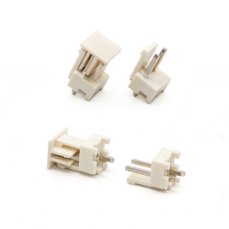
First, let’s ground ourselves in the basic structure of an FPC connector, because the mating angle only makes sense when you understand how the two parts work together. An FPC connector has two core components: the housing (usually made of high-temperature plastic, polyimide, or liquid crystal polymer, LCP, which can withstand soldering heat and repeated use) and the contact terminals inside the housing—tiny, precision-machined metal pins or sockets that carry electrical signals and power. The FPC itself is that thin, bendable circuit board, with copper traces sandwiched between flexible insulating layers, that plugs into the connector to form a complete circuit.
When you “mate” an FPC connector, you’re not just pushing the FPC straight into a slot. That would be impossible for most designs, because FPC connectors are almost always built for compact spaces, and the FPC is too thin and flexible to insert without a controlled bend. Instead, you lift a lever on top of the connector housing (most common for surface-mount or through-hole FPC connectors) to open the terminal contacts, slide the end of the FPC into the housing’s slot at a specific angle, and then close the lever to lock the FPC in place, pressing it firmly against the terminals. That angle at which you insert the FPC into the housing before locking is what engineers call the mating angle.
Wait, but why is it not just a straight 90-degree angle? Let’s clarify with an example. If you have a standard top-entry FPC connector (one where the lever sits above the slot), the slot is aligned parallel to the printed circuit board (PCB) the connector is soldered to. To slide the FPC into that slot, you can’t hold the FPC flat against the PCB and push straight down—that would bend the FPC in a sharp, stress-prone way and miss the slot entirely. Instead, you lift the FPC end up at an angle of 10 to 30 degrees relative to the PCB’s surface, slide it into the slot, then lower it flat against the terminals. That initial insertion angle is the mating angle, and it’s a critical design parameter, not just a random step in assembly.
Now, let’s get into the technical specifics that matter for part performance. The mating angle isn’t just a single number that works for every connector. It’s specified by the manufacturer for each FPC connector model, and it’s tied directly to the terminal geometry and housing design. For instance, a low-profile FPC connector (used in slim smartphones, where every millimeter counts) will have a smaller mating angle—often around 15 to 20 degrees—because the slot is shallow, and the lever has limited travel to lock the FPC. A higher-current FPC connector, used in industrial motor controls where power needs to flow through thicker traces, might have a slightly larger mating angle, up to 30 degrees, because the FPC itself is thicker, so you need a wider opening to slide it in without damaging the traces.
Here’s where I see a lot of engineers make a mistake: they assume any mating angle will work as long as the FPC fits. That’s not true. If you insert the FPC at an angle that’s too steep—say, 40 degrees for a connector rated for 20 degrees—you risk bending the FPC’s copper traces beyond their fatigue limit. Over thousands of insertions (or even just one initial assembly), that sharp bend can crack the trace, leading to intermittent connections or total circuit failure. On the flip side, if you use an angle that’s too shallow, you won’t fully seat the FPC in the housing, so the terminals won’t make proper contact. That leads to signal dropout, overheating, or even arcing in high-voltage applications—no small risk when you’re building a medical device or an automotive sensor.
I learned this lesson early in my business, back when we had a customer building wearable fitness trackers. They’d sourced a cheap FPC connector from a local supplier, no spec for mating angle listed, and they were assembling 10,000 units a day. Within a week, 12% of the units were failing after 1,000 uses, because their assembly team was inserting the FPC at a slightly steeper angle than the connector was designed for. The thin FPC traces (only 0.05mm thick) were cracking at the bend point during repeated opening and closing of the tracker’s screen. When we took a look at their design, we saw that the original connector’s housing had a mating angle tolerance of ±2 degrees—something the cheap supplier had never mentioned. We switched them to our standard low-profile wearable FPC connectors, which had a clearly specified mating angle of 18 ±1 degrees, and adjusted their assembly tools to hold that consistent angle. The failure rate dropped to under 0.1% within a month. That’s when I realized how much a simple, often overlooked spec like mating angle can impact quality and reliability.
Now, let’s talk about tolerance. Mating angle is always given with a tolerance, usually ±1 to ±3 degrees, depending on the connector’s application. That tolerance exists because no assembly process is perfectly precise, but it also ensures that the FPC seats correctly without stress. For aerospace or medical applications, where reliability is non-negotiable, the tolerance is often even tighter—±0.5 degrees, for example—because a small variation in angle can lead to catastrophic failure in a critical system. If you’re working on a consumer product like a wireless headphone, the tolerance might be wider, ±3 degrees, because the application is less critical, but even there, sticking to the specified angle will extend the connector’s lifespan.
Another factor tied to mating angle is insertion force. The mating angle directly determines how much force you need to slide the FPC into the connector housing. If the angle is set correctly, the insertion force should fall within the connector’s rated range—usually between 0.5 N and 5 N, depending on size. Too steep an angle means you’ll need more force to insert the FPC, which can damage the FPC, bend the terminals, or even break the housing. Too shallow an angle means you’ll have to push harder to seat the FPC, leading to the same issues. When we design our FPC connectors, we simulate the insertion process with finite element analysis (FEA) to calculate the optimal mating angle, ensuring that insertion force is low enough for automated assembly (which is what most manufacturers use now) but high enough to prevent the FPC from coming loose due to vibration.
Wait, did I mention automated assembly? Most modern FPC connectors are assembled with pick-and-place machines, not by hand, especially for high-volume production. Those machines are programmed with the exact mating angle for the connector model. If a machine is programmed with the wrong angle, you’ll get misinserted connectors, which are a nightmare on the production line. That’s why clear documentation of the mating angle is not just helpful—it’s essential for production efficiency. We include mating angle specs on every datasheet for our FPC connectors, along with CAD models that show the angle dimension, so customers can load that data directly into their assembly machines without guessing.
Let’s also address a common confusion: mating angle vs. insertion angle. Some people use these terms interchangeably, and in most cases, they are referring to the same thing—the angle at which the FPC is inserted into the connector housing. But there’s a subtle distinction: the mating angle is the angle of the FPC relative to the connector’s PCB surface, while the insertion angle might sometimes refer to the angle of the FPC relative to the connector’s housing slot. It’s a small difference, but for precision design, it’s good to clarify that the mating angle as a spec is always defined relative to the PCB or housing mounting surface, per industry standards from organizations like the IPC (Association Connecting Electronics Industries).
So, how do you select the right mating angle for your project? First, check the connector manufacturer’s datasheet. Don’t assume all FPC connectors have the same mating angle—we’ve seen models from different suppliers for the same application with mating angles ranging from 15 to 25 degrees, which makes a huge difference in assembly and reliability. Second, consider your FPC’s thickness and the number of insertions. If you need a connector that can handle 10,000+ mating cycles (common in consumer electronics that fold, like foldable phones), a smaller mating angle reduces stress on the FPC, so it’s a better choice. For a one-time mating application, like a sensor that’s sealed after assembly, a slightly larger angle is fine, just make sure it’s within the manufacturer’s tolerance.
Third, think about your assembly process. If you’re doing manual assembly, a wider tolerance mating angle might be easier for your technicians to work with, but if you’re using automated pick-and-place, you need a clearly specified, repeatable angle to avoid downtime. We once had a customer with a small production run of industrial controllers, done in-house with manual assembly. They’d sourced a connector with a 15 ±3 degree mating angle, which was perfect for their technicians, who could easily feel when the FPC was inserted at the right angle, and their failure rate was negligible. Another customer doing 1 million units a year needed a tighter tolerance, so we provided them with a 20 ±1 degree mating angle, and their automated assembly lines picked up the CAD data seamlessly, with zero issues related to mating angle.
Now, I want to be transparent, as a supplier, about what we do to ensure our mating angles are accurate. We test every batch of FPC connectors we ship using 3D metrology equipment to measure the slot angle and the lever travel, because even a 1-degree variation can lead to problems. We also publish our datasheets with clear diagrams that show the mating angle, not just a number, so there’s no room for misinterpretation. We get calls every week from engineers who messed up their spec because they used a generic connector datasheet that didn’t define the mating angle clearly, so part of our job is walking them through that, answering questions, and making sure they have the right part for their needs.
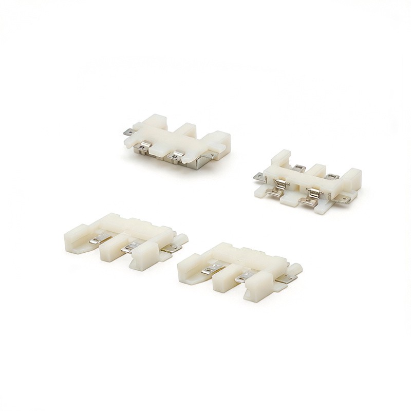
If you’re in the middle of designing a project, and you’re not sure what mating angle you need, or you’re having issues with connector reliability, let’s connect. As an FPC connector supplier, I’ve worked with teams building everything from small wearables to industrial heavy equipment, and I can help you select the right connector with the correct mating angle for your application, no matter how niche your project is. Just reach out to our team to discuss your requirements.
Header Connector References
IPC-2221: Generic Standard on Printed Board Design. Association Connecting Electronics Industries, 2023.
Flexible Printed Circuits (FPC) Connectors: Design and Application Guidelines. TE Connectivity, 2022.
Mating Cycle and Mechanical Reliability of FPC Connectors. Hirose Electric Co., Ltd., 2021.
Wenzhou JKUN Connector Co., Ltd.
Address: No.2667, Ningkang East Road, Yueqing City, Zhejiang Province, China
E-mail: sales@cnjkun.com
WebSite: https://www.jkunjcj.com/
